PROJECT: communications system
The communications system links the brain-computer system and the robotic system (Figure 6), which is composed by two clients (the BCI client and the robot client) and a link server that concentrates the information flow and confers scalability to the system. All the connections among logical components are TCP/IP.
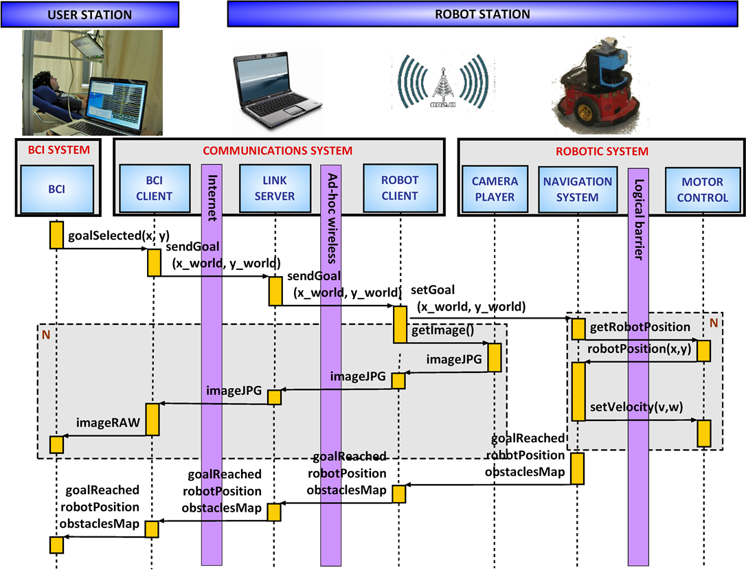
Fig. 6. The figure shows the abstraction layers: the first row represents the two stations, the second row the computer hardware and the links between them, whereas the third row represents the logical components. Below there is a typical event trace of a goal selection in the robot navigation mode. The flow of information and its direction are illustrated by arrows. Vertically, time increases downward, and the vertical rectangles below boxes stand for a code execution. The dark boxes enveloping certain portions of code and information exchange represent an iterative execution task.
The BCI client is multiplexed in time with the BCI system with a period of roughly 30 ms and communicates with the link server through an Internet connection. The robot client encapsulates the autonomous navigation system as a thread, and synchronizes the orders to the camera and to the navigation system. This client communicates with the link server with an ad-hoc wireless connection.
Regarding the information transfer, on the one hand the navigation system transfers to the BCI the map model of 400 bytes and the robot location within the map of 12 bytes. Furthermore, the images captured by the camera are compressed in the jpeg standard format, obtaining an image size of 30 kbytes (in our experiments we transferred 10 images per second). On the other hand, the BCI sends the goal location when it is computed (of 8 bytes). In execution, the upper bound for the information transfer rate is close to 300 kbytes per second, adecuated for the typical order of Mb bandwidth of internet networks.
Regarding the time critical tasks in this integration, the robot motion controller has been encapsulated in a dedicated computer (low-level computer) with a real-time operative system. The autonomous navigation system has been integrated in another dedicated computer, and integrated within a task-based system with timeouts to preserve the computation cycle. Both tasks communicate within a synchronous periodical task of 0.2sec, where the navigation system reads from the client the goal location, the laser measurement, and requests the odometry to the low-level computer. Then, it executes the mapping and planning module and sends the translational and rotational velocity computed to the low-level computer.