PROJECT: brain-computer system
This section describes the brain computer system, which is located in the users station (Figure 1).
Neurophysiological protocol and instrumentation
The neurophysiological protocol followed in our study is based on the P300 visually-evoked potential [10], which is usually measured in humans EEG. In this protocol, the user focuses his attention on one of the possible visual stimuli, and the BCI uses the EEG to infer the stimulus that the user is attending to. The P300 potential manifests itself as a positive deflection in voltage at a latency of roughly 300 ms in the EEG after the target stimulus is presented within a random sequence of non-target stimuli (Figure 2). The elicitation time and the amplitude of the potential are correlated with the fatigue of the user and with the saliency of the stimulus (in terms of color, contrast, brightness, duration, etc) [10].
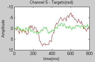
(a) |
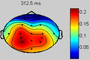
(b) |
Fig. 2. (a) Typical P300 response. The dark line shows the EEG activity in one channel (elicited by the target stimulus), and the light line to the non-target one. (b) Topographical plot of the EEG distribution in the scalp at 300 msec. The area with more activity (mid-low part of the scalp) is in the parietal lobe, where the P300 potencial is elicited.
The general instrumentation of the BCI is a commercial gTec EEG system (an EEG cap, 16 electrodes and a gUSBamp amplifier). The electrodes were located at FP1, FP2, F3, F4, T7, T8, C3, C2, C4, CP3, CP4, P3, P2, P4 and OZ according to the international 10/20 system as suggested in previous studies [11]. The ground electrode was positioned on the forehead (position Fz) and the reference electrode was placed on the left earlobe. The EEG was amplified, digitalized with a sampling frequency of 256 Hz, powerline notch filtered and bandpass filtered between 0.5 and 30 Hz. The signal recording and processing, and the graphical interface were developed under the BCI2000 platform [12], placed on an Intel Core2 Duo @ 2.10GHz with Windows OS.
Graphical interface
The graphical interface has two functionalities: (i) it displays the visual information used as the base for the users action selection, and (ii) it develops the stimulation process to elicit the P300 visual evoked potential. Both functionalities are described below:
1) The visual display: The base of the visual display is the live video received by the camera placed on the robot. This video is augmented by overlapped information related to the two teleoperation modes: the robot navigation mode and the camera control mode.
The robot navigation mode allows the user to control the robot motion (Figure 3).
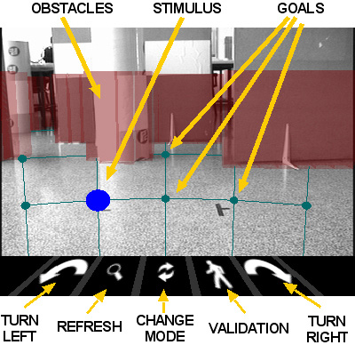
Fig. 3. Visual display in the robot navigation mode
Overlapped to the video, the environment obstacles are displayed by semitransparent walls, represented by a 3D reconstruction built from the 2D map constructed in real time by the autonomous navigation technology. Furthermore, there is a grid of destinations over the floor that the operator can select at distances (1,5m, 2,5m, 4m) x (-20º, -10º, 0º, 10º, 20º). The obstacles hide the unreachable destinations of the grid. The icons in the bottom part represent the following actions, from left to right: (i) turn around 45º to the left the robot; (ii) refresh the live video to perform a selection based on a more recent information of the environment; (iii) change to the camera control mode; (iv) validate the previous selection; and (v) turn around 45º to the right the robot.
The camera control mode allows the user to control the pan/tilt orientation of the camera to perform a visual exploration of the environment (Figure 4).
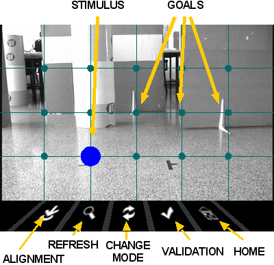
Fig. 4. Visual display in the camera control mode
Overlapped to the video there is a grid of locations, uniformly placed in a 2D plane in front of the camera, that the user can select to orientate the camera in that direction. The icons in the bottom of the screen represent the following actions, from left to right: (i) align the robot with the pan camera orientation and change to the robot navigation mode; (ii) refresh the live video; (iii) change to robot navigation mode; (iv) validate the previous selection; and (v) set the camera to its initial orientation.
2) Stimulation process: The graphical interface stimulates the options of the visual display to elicit the P300 visual-evoked potential when the operator is concentrated on a given option. An option is 'stimulated' by flashing a circle on a grid intersection or icon in the visual display. One sequence of the stimulation process is a stimulation of all the options in random order as required by the P300 oddball paradigm. In order to reduce the magnitude of the posterior classification problem and the duration of a sequence, we follow here the Farwell and Donchin paradigm [13]: the flashing of the stimulus is done by means of rows and columns instead of flashing each option individually. Thus, there are 9 stimulations (4 rows plus 5 columns) per sequence. We have kept constant the topology of the two teleoperation modes to have an uniform stimulation pattern. All the elements of the display can be customized in terms of color, texture, shape, size and location; and all the scheduling of the stimulation process (time of exposition of each stimulus, inter-stimulus durantion and inter-sequence duration) can be modified to equilibrate the user capabilities and preferences with the performance of the system.
Stimulation process example (number of sequences = 4)
Pattern recognition strategy
The pattern recognition is a supervised learning module to recognize the P300 evoked potential, and thus, to infer the stimulus that the user is attending to. The first step is to train the system via offline experiments, where the user faces the graphical interface with the stimuli described above. In this process, the user concentrates on a predefined sequence of selections that covers all the classes. The data is recorded and used to train the classification algorithm using a supervised learning technique with two steps described next.
1) Feature extraction: The P300 signals are characterized in the time domain so the information is in its waveform and latency times. Following [11], we recorded for each EEG channel 1sec of samples after each stimulus onset. Then, these segments of data were filtered using the moving average technique, and decimated by a factor of 16. The resulting signals were plotted and the channels with the best P300 response were selected by visual inspection. Finally, the data segments of each channel were concatenated creating a single feature vector for the next stage.
2) Classification algorithm: In our system, the P300 signal is elicited for one of the four rows and the five columns during one sequence of the stimulation. Thus, there are two classification problems of 4 and 5 classes. For each one of these problems we used StepWise Linear Discriminant Analysis (SWLDA), extensively studied for P300 classification problems [11], and well-known for its good results obtained in online communication using visual stimulation. In our system, we have obtained a performance higher than 90% in less than an hour of training with SWLDA
Execution protocol
The way the subject utilizes the options provided by the visual display is modeled by a finite state machine (Figure 5). Initially the state is Waiting for command, and the system starts in the robot navigation mode. The BCI develops the stimulation process and, if there are no errors in the pattern recognition, the option the user was concentrated on is selected (notice that there are different options according to the refresh one that simply refreshes the live video), the state turns to Waiting for validation. A new stimulation process gets a new option. If the option is the validation one, the last command is transferred to the robotic system and the state turns to Robotic system: performing action; otherwise the stimulation process starts again until a command is selected and later validated. While the state is Robotic system: performing action the robot performs the desired action and the graphical interface displays the live video. When the BCI system receives an external flag coming from the robotic system informing that the execution of the action has finished, the video transfer stops and the state turns to Waiting for command, starting the process again.
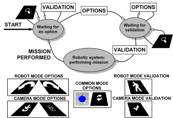
Fig. 5. Finite state machine that models the execution protocol.